To learn more about low-level programming and NASM (Netwide Assembler), I created BasicBoot, a simple bootloader project. In this post, I’ll walk you through my process, the challenges I faced, and key snippets of code to show how it all works.
Why Write a Bootloader?
The main goal of this project was to understand the basics of bootloading and real-mode programming. By working with BasicBoot, I aimed to learn:
- NASM Assembly Language: Gaining some kind of fluency in NASM.
- Bootloading Concepts: Understanding how a system transitions from hardware initialization to software.
- BIOS Interrupts: Using real-mode BIOS services to interact with the hardware.
BasicBoot has three primary features:
- Boot from a disk.
- Load a kernel into memory.
- Display a message on the screen.
Breaking Down BasicBoot
The Boot Sector
The BIOS loads the bootloader into memory at 0x7C00. To ensure compatibility, the first step was initializing the code and setting up a stack. Here’s how I did it:
bits 16
org 0x7C00       ; BIOS loads the boot sector here in memory

start:
    ; Set up the stack
    xor ax, ax
    mov ds, ax
    mov es, ax
    mov ss, ax
    mov sp, 0x7C00
Explanation:
bits 16: Specifies 16-bit real mode.org 0x7C00: The location where the BIOS loads the bootloader.- Stack Initialization: The stack pointer (
SP) is set to0x7C00, just below the bootloader code, ensuring stable execution for future calls and interrupts.
Loading the Kernel
The bootloader’s primary job is to load the next stage: the kernel. Here’s the code to read the kernel from the disk:
    mov si, 0x2000     ; Address where the kernel will be loaded
    mov bx, si         ; Store the address in BX

    ; Read the kernel from the disk
    mov ah, 0x02       ; BIOS function to read sectors
    mov al, 1          ; Read one sector
    mov ch, 0          ; Cylinder 0
    mov cl, 2          ; Sector 2
    mov dh, 0          ; Head 0
    mov bx, si         ; Buffer to read into
    int 0x13           ; Call BIOS interrupt 0x13

    jmp bx             ; Jump to the kernel
Explanation:
mov ah, 0x02: Sets the BIOS disk service to read a sector.mov al, 1: Reads one sector from the disk.mov bx, si: Specifies the memory buffer where the sector will be loaded (0x2000).int 0x13: Executes the BIOS disk read operation.jmp bx: Transfers control to the loaded kernel.
Testing this part was annoying since all the code looked perfect, but it everything kept crashing on boot. I assumed that there was an error in my qemu, but after re-installing it, I realised had typo in the kernel addressing. After fixing this stupid error, I found everything seemed to look fine. no errors :P
The Kernel
Once loaded, the kernel is executed. Here’s the kernel code that displays a text message:
bits 16
org 0x2000

start:
    mov si, text         ; Load the address of the text into SI
    call print_string    ; Call the print function

hang:
    jmp hang             ; Hang the system

print_string:
    mov ah, 0x0E         ; BIOS teletype function
.next_char:
    lodsb                ; Load the next byte into AL
    cmp al, 0            ; Check for the null terminator
    je .done             ; If null, end of string
    int 0x10             ; Print the character
    jmp .next_char       ; Repeat
.done:
    ret                  ; Return to the caller

text db 'This text is displayed by the bootloader!', 0
Explanation:
mov si, text: Points to the message string.lodsb: Loads the next character from memory (SI) intoAL.int 0x10: Prints the character inALusing the BIOS teletype service.hang: Prevents the CPU from running into undefined memory.
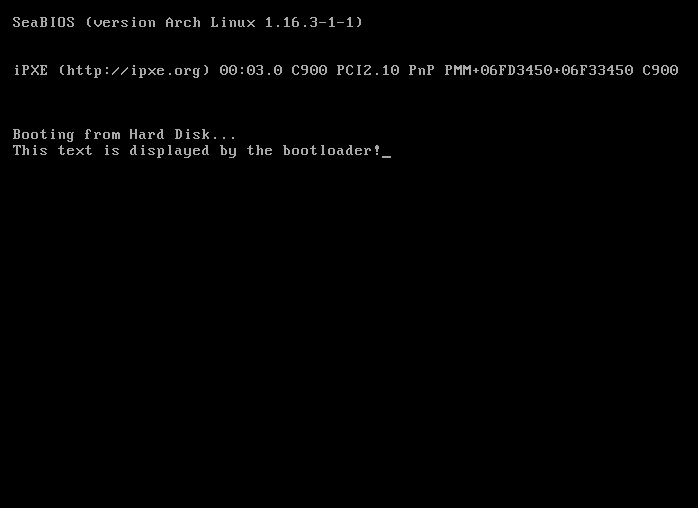
Seeing text appear on the screen was super cool. It proved that the bootloader and kernel were functioning correctly. Once I saw this I pretty much felt like the spiritual successor of Terry Davis
Final Touch: The Boot Signature
The boot sector must end with a 2-byte signature (0xAA55) for the BIOS to recognize it as bootable:
times 510 - ($ - $$) db 0 ; Pad with zeros to 510 bytes
dw 0xAA55                 ; Boot signature
This ensures the bootloader fills exactly one sector (512 bytes).
Building and Testing
Here’s how I built and tested BasicBoot:
- Assemble the bootloader and kernel:
1
2
nasm -f bin basicboot.asm -o basicboot.bin
nasm -f bin text.asm -o text.bin
- Combine them into a bootable image:
1
cat basicboot.bin text.bin > boot.img
- Test with QEMU:
1
qemu-system-x86_64 -drive format=raw,file=boot.img
Using QEMU saved time debugging compared to real hardware testing and made it easy to iterate on the code. Here is what the end result should look like (If everything compiles with no errors)

What I Learned
- Real-Mode Programming: Working in 16-bit mode helped me understand memory segmentation and BIOS interrupts.
- Debugging Patience: Every issue taught me something new about how computers work at a fundamental level.
What’s Next?
While BasicBoot is a simple bootloader, it’s sparked ideas for future projects:
- Transitioning to protected mode for modern 32-bit or 64-bit capabilities.
- Supporting multiple kernel images.
- Building a basic file system.
Conclusion
Creating BasicBoot was a rewarding experience. It deepened my understanding of how computers boot and gave me newfound respect for the engineers who build operating systems. Whether you’re an OS enthusiast or just curious about low-level programming, I highly recommend diving into bootloader development.
If you’d like to see the code or try it yourself, feel free to check out my GitHub repository].
Thank you for reading!